Your sites work as one
Main office, sub-office and substation joined by fiber, so your systems can reach every site.
ProofTwo phases, three sites connected.
Case study · Fiber Optic Cabling
Electric cooperative
Joined by fiber, in two phases
Visayas, Philippines
A regional electric cooperative in the Visayas engaged LMI to link its main office, its sub-office and a substation with fiber. The work ran in two phases, accepted in February 2025 and September 2026.
LMI surveyed the route, mapped it pole by pole, built the aerial link and proved it with OTDR testing before each handover.
On recordSigned acceptance test and certificate for each phase.
Surveyed the route and recorded every pole with GPS coordinates on aerial maps.
Documented the design: route maps, a splicing diagram and a link budget.
Hung 8-core single-mode cable on the approved poles, spliced it into sealed enclosures and installed switches with UPS power.
Tested with OTDR, link loss, ping and SFP checks, then a signed acceptance test and certificate.
Site challenge
Two phases, three sites
Schematic, not to scale. Names withheld.
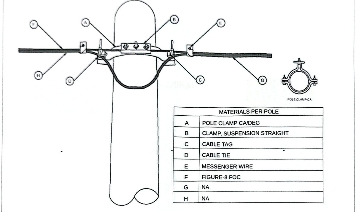
Fiber-to-pole installation detail, from the as-built design. The design package also covers aerial route maps, a splicing diagram and a link budget.
Digital transformation requires solid infrastructure.
Every new system depends on the infrastructure beneath it. LMI builds that foundation so your team can find it, maintain it and trust it.
Main office, sub-office and substation joined by fiber, so your systems can reach every site.
ProofTwo phases, three sites connected.
A documented route and tested links give new systems a network they can rely on.
ProofEvery active link tested in phase 2.
Every pole is recorded and slack loops are built in, so a fault can be located and repaired.
Proof125 poles recorded; 15 maintenance loops.
Your team witnesses the tests and signs the acceptance test before you depend on the link.
ProofSigned acceptance in both phases.
Also from LMIThe rest of the infrastructure a digital operation runs on: Network refresh · Structured copper cabling · Core switching · Managed firewall and Wi-Fi · Managed CCTV · Access control and turnstiles · Lightning protection · Electrical works · Turnkey infrastructure projects
Getting your sites ready for what’s next? Start with a survey.
Contact us at lori@onelmi.comClient and site names withheld. Product names are trademarks of their owners.
LMI Corporation · Bacolod City, Negros Occidental, Philippines